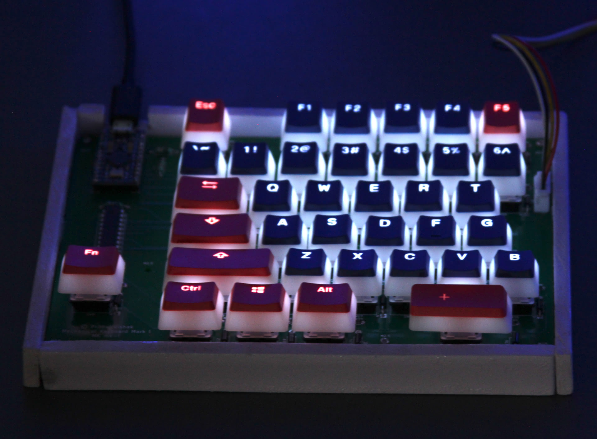
Building My Mechanical Keyboard
By Prithvi Vishak
Created November 7th, 2021
My dad and I use our computers a fair bit, him for his work, and me... also for my work. Let's keep it at that. Anyway, over the past couple years, the both of us had been through our fair share of keyboards. My dad had used a Microsoft Natural Elite keyboard (from 1998) till about 2015, when he got himself a Logitech Wave. I had been shuffling between an Apple Magic keyboard, that ancient Logitech keyboard that appears in every TV cop drama titled "NCIS", and another newer but still run-of-the-mill wireless Logitech keyboard.
The Logitech Wave was okay until its keys got really clunky. Same with my two Logitechs. The Magic keyboard wasn't clunky, but it had chiclet keys with a fixed, highly uncomfortable incline. I eventually got out my dad's old Microsoft keyboard and used that, until it too started to feel clunky.
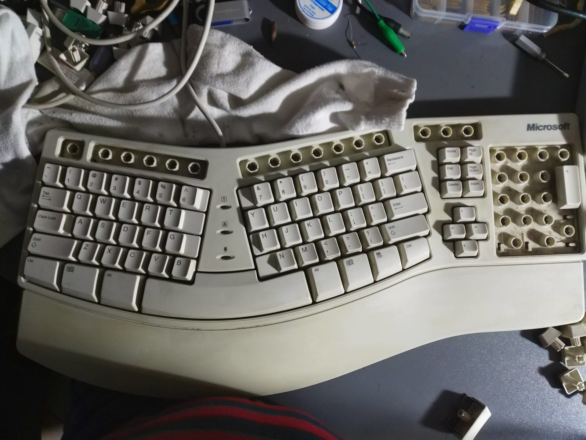
Yeah...
Around December 2020, my dad and I decided that it was time to splurge on some good peripherals. We heard about how mechanical keyboards were less clunky and longer-lasting than regular membrane keyboards, so we steered the mechanical route. The Microsoft Natural spoilt standard, joined (?) keyboards for us, so we were on the lookout for split mechanical keyboards. It quickly became clear that the only viable (viable = ships to India) option was the Kinesis Freestyle. It has a $100 price tag... in the US. But in India, it was about three times that amount (including shipping and customs). So that prospect died pretty quick, but from its ashes arose a new one, like Mozilla from Netscape:
We would make our own.
Rather, I would make our own. Indeed, plenty of people have done it before, and at their core, keyboards are fairly simple devices. An attainable goal indeed. Here's how it went. Before you continue reading, I'd like to enunciate that this isn't a detailed, step-by-step "How to", but rather a general "How I did". This article aims to give you some insight into my keyboard building process, in the hopes that you glean a helpful idea or two for your own build. There are links to resources I found helpful.
General Plans
My dad and I deliberated and settled on what exactly we wanted in our keyboards in terms of hardware. We decided to go for the standard staggered key placement (none of that ortholinear voodoo), while getting rid of some keys we never used (like Scroll Lock) and moving the function key way out into the countryside to keep it away from Ctrl, GUI (the official name for the "Windows", "Command ⌘", and "Special" keys), and Alt. We also wanted backlighting, because it's cool (and so my dad can see the legend at night, but mostly because it's cool).
Hardware Overview
For switches, we went with Gateron Milky Reds, because they were low actuation force, and, well, available (and I don't regret the decision). Since we don't have the means to mill custom plates, we decided to go the PCB route, and purchased the 5-pin PCB-mount variety of the switches. We splurged a little on our keycaps, going for Ducky Puddings (PBT plastic, double-shot). As for stabilizers for the longer keys, we ended up not buying any, mostly because they were too expensive, and because the longest keys on our boards would be the small 2u spacebars. Given that our low-actuation force switches are buttery smooth, stabilizers just weren't necessary.
I decided to use Ardino as my platform of choice for the logic, since I'm pretty familiar with it. Each half of the keyboard has one Arduino, with the left being the main half. I call the left side the main half, because that's where most of the brains of the keyboard sit. The left half has an Arduino Pro Micro with the Atmel ATMega 32u4, a microcontroller with built-in USB functionality (most other Arduinos like the Nano have a USB-to-serial converter between the USB port and the microcontroller, which cannot expose itself as a keyboard). The good folks at Arduino have already written an easy-to-use Keyboard library for the Pro Micro, so all my code has to do is scan a button matrix, and tell the keyboard library which key to press when. Not too difficult. The left half is the one with the USB cable going to it.
The second half has an Arduino Nano, because Nanos are cheaper and have more pins (which I needed, with the right having 49 keys against the left's 36). The two halves communicate over UART/serial.
The backlights are controlled not by the Arduinos directly, but through MAX7219 LED multiplexer ICs. Each requires three data lines, which is a huge step up from the 12 and 14 extra pins required of each Arduino if they were to be controlled directly. Each LED requires its own current-limiting resistor, and with me using through-hole diodes, I wouldn't have had enough space between switches for through-hole resistors. So, I went took my first step into the world of SMD soldering, and procured some 1206 SMD resistors.
One thing I found odd was that standalone MAX7219 ICs were expensive and hard to come by, but there were cheaper dot matrix LED matrices, that had these ICs in sockets. So, I just bought those, and unseated the ICs.
Electronics Design
I began my electronics prototyping from the fact that a keyboard is essentially a big button matrix. Hooking up a few buttons to an Arduino, I got a quick 2x2 matrix working, using diodes to prevent ghosting (see this incredibly-detailed Sparkfun tutorial). This was pretty much all the hardware testing I could do with the stuff I had at home.
I had messed around a while ago in Autodesk Eagle EDA, and it was fairly intuitive. Unfortunately, the free version of Eagle limits you to an 80 sq. cm board area. That just wouldn't cut it for a keyboard. Thankfully, I found out about KiCad, which is free and open-source, with no such limits. Armed with information from online tutorials, I started with a schematic of the left, and main, half of the keyboard.
Anyway, the schematic was again fairly straightforward. All I had to do was make a grid of switches with each row and column hooked up to a pin on the Arduino. I went for for a 6x6 matrix on the left side, and 7x7 on the right, to make optimal use of the pins available to me. The MAX7219 was easy to wire up too. Nothing hard there. Only after my PCBs had been fabricated did I realize that some of my connections in the schematic were not actually complete. These missing connections percolated down to the PCB, and I ended up having to bodge them with wire.
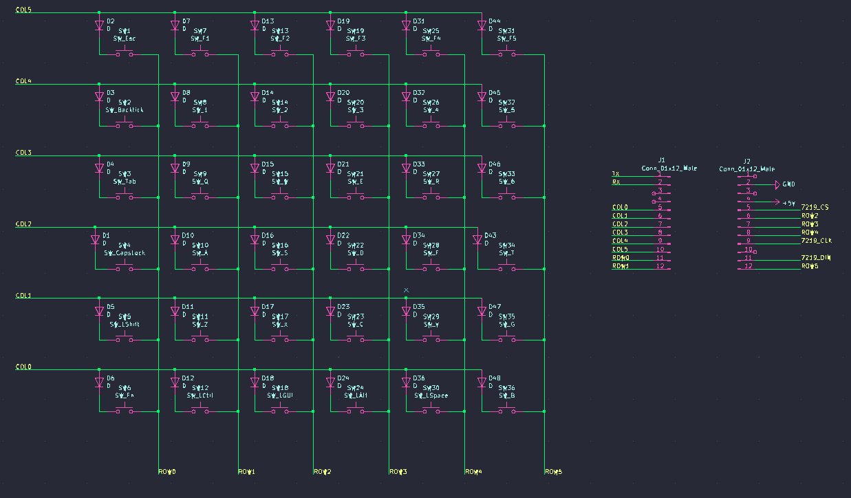
The left switch matrix, with all errors corrected
Instead of using proper Arduino footprints for the schematics, I just placed headers for them to plug into. Another thing I wished I had noticed was that in one schematic, one header was flipped. I also (at the worst time) found that I had also flipped every single diode on the left side. One hiccup (not really an issue) is that I had more rows and columns in my switch matrices than digital pins on the Arduinos. It's fairly well known that most of the analog input pins on AVR Arduinos can also be used as digital pins. Unfortunately, that most bit me in the behind. The Arduino Nano's A6 and A7 pins are analog inputs only, again a fact I found out only when I had two dead rows on my otherwise complete keyboard.
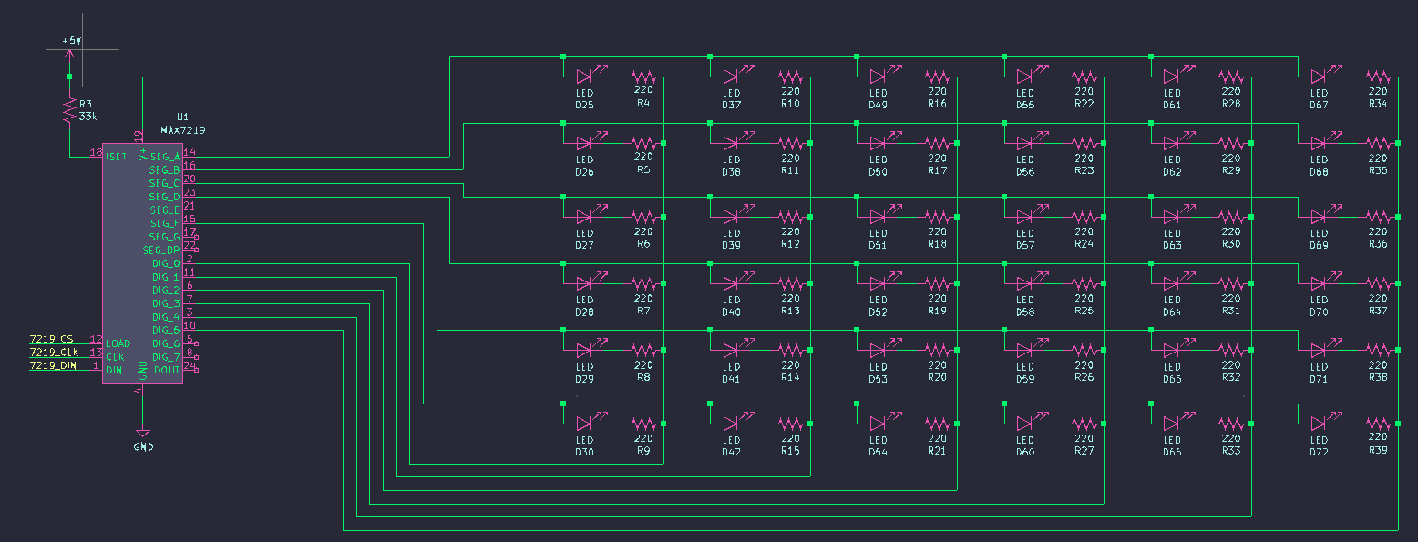
The left LED matrix, with no errors to start with ßD
KiCad doesn't have footprints built-in for Cherry MX-style keyswitches. Of course, the open-source community came to my rescue again. I used this excellent library.
Laying out each component on the PCB was tedious but easy. The keyswitch PCB footprints had appropriately-spaced borders, and simply snapped together. Any doubt I had about spacing was cleared in this Deskthority thread. There were many routes to make, so I got lazy and used an autorouter (particularly the FreeRoute autorouter) for all the traces. I then removed the messy connections and did them by hand. To be honest, I don't really regret using the autorouter. Hand-routing would have taken me way too long, and may have required me to use more vias and layers than necessary. If I had to design another keyboard from scratch, though, I would try to do it myself. I also made some of the power traces a little thicker, though I doubt it was necessary. 500mA, the maximum current a to-spec USB 2.0 port can provide, is much lower than the default trace width's max current rating.
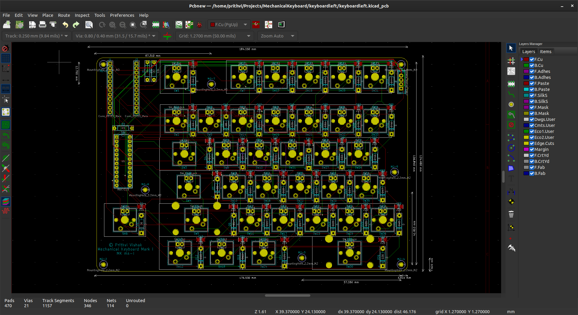
The left half's PCB layout, with errors corrected. Please don't kill me, Dave Jones!
I tracked down a local fabricator to get my designs printed. They were definitely more expensive than some Chinese ones for hobbyist-tier fabrication, but with trade sanctions and whatnot, lead time was huge, and I preferred supporting a local business anyway. I was pretty clueless as to what settings I should use before submitting my Gerber files, but their customer support was very helpful, and I have a feeling I'm not the first hobbyist that's reached out to them.
Electronics Assembly
Once my PCBs arrived, I did nothing but solder for the next two days. As mentioned earlier, I painstakingly debugged my hardware and eventually fixed everything. Let's just say, hooray for bodge wire and solder suckers (Just kidding, solder suckers are completely useless. The only way to get components out is by heating up the pins, then prying them out from the other side with tweezers or your bare hands). Then, I had to debug my software too. While I had written more-or-less complete firmware while the PCBs were being fabricated, I had no way to test everything on a breadboard. That was another headache.
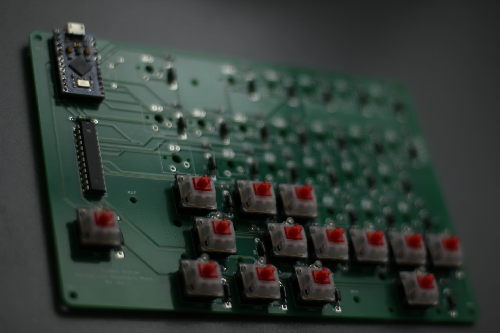
Ain't she a beaut?
One noteworthy thing I did was desolder the onboard LEDs and linear voltage regulators from both Arduinos, because they were completely unnecessary power drains. I also disabled the ADCs in software.
After a lot of work, the electronics for my keyboard were finally done. Making my dad's took much less time and hair-pulling because I already knew about all the flaws.
Firmware
You can find great free and open-source keyboard firmware(s?) out there, like QMK, with really cool features. But porting something like QMK to my keyboard seemed like a pretty big task, and real men write their own keyboard firmware.
To start off, the switch matrices' rows and columns are all connected to Arduino digital pins. The rows are inputs and the columns are outputs. In their default state, the rows are pulled high by the Arduino's internal pullup resistors, and the columns are set high. Scanning the matrix goes column-by-column, so when a column is to be scanned, it is set low. If a key is pressed, the row of the key is pulled low, and the keypress is registered.
The Arduino Pro Micro on the left half contains mappings for matrix positions to keypresses. Each individual mapping is a layer. Layers can be switched between with specific actions. For example, the default layer is my custom Dvorak layout, while there are layers for vanilla QWERTY, and a Function layer for when the function key is pressed. The only limiting factor to the number of layers I can have is RAM (I haven't found a way to have layers stored in flash without sacrificing functionality), but even then I chomp through over 70% of the Pro Micro's 2.5k with three layers. The Arduino Nano on the right simply scans the matrix and reports row number, column number, and state to the left, so that all the layout configuration can be done on the left.
I have five backlight modes: off, bright, brighter, brightest, and random. The different brightnesses can be set by the Arduino on the MAX7219, requiring no effort on the Arduino's part to manually PWM the LEDs. The random mode simply turns individual LEDs on and off at random. This does require the Arduinos to actively specify which LEDs should be on.
I like the way my firmware only needs to be flashed to one side of the keyboard for layout changes (backlight animations still need to be programmed into both sides). Unfortunately, different firmware is required for each side (though the right's is super simple). There are some characters I require that aren't available on a standard English keyboard, like some letters with diacritics. For those, I have the Unicode character shortcut auto-typed. In case you aren't aware, you can input unicode characters on Linux by pressing Shift+Ctrl+U, then typing in the hexadecimal UTF-8 code point for the character, then Space or Enter. Windows and MacOS have similar functionality, but different keybindings.
Case
Never in my design process did I try to make the PCBs compatible with any retail cases that are available, thinking that I could make my own crude cases once I had working electronics. I ended up making an MDF one for my keyboard, and 3D-printing a base for my dad's. Right now, large portions of the PCB still remain exposed on top, but I am designing some covers for them.
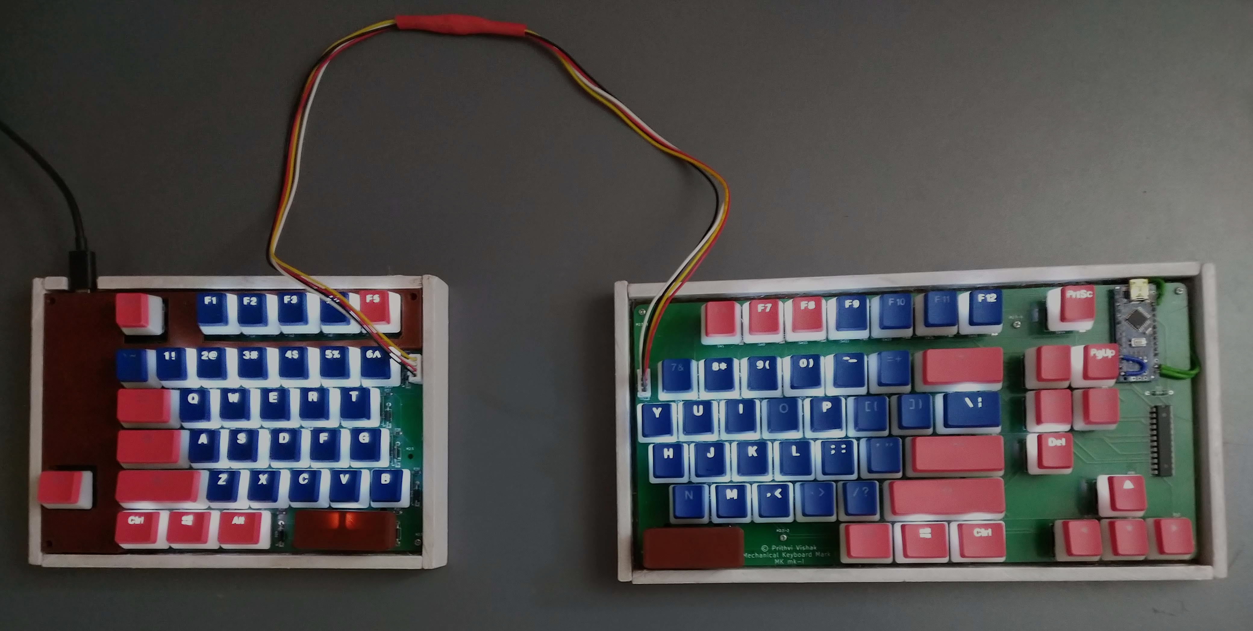
It may look like a 5-year-old's craft project, but it is very sturdy.
Conclusion
I hope you found this article somewhat insightful, and helps you build your dream keyboard. I'll let you go with this one statement: Your keyboard will never be the best. Mine will always be vastly superior. Why? Fn+9:
¯\_(ツ)_/¯
